10.8 CLUSTERING OF LIQUID PROPELLANT ROCKET ENGINES
The idea of obtaining higher thrust levels expeditiously through combination of several smaller rockets probably is as old as rocketry itself. To today's liquid rocket vehicle and engine builders the topic of clustering still causes spirited debates, which reached a peak in March 1952 when Collier's published an article by Dr. von Braun in which a space vehicle was described as having a first stage powered by a cluster of 51 turbopump-fed rocket engines. The debates invariably hinge around the deceivingly simple question: is higher overall reliability obtained through combination of a number of well-developed smaller engines, or through application of one large, specially developed unit. The answer is not simple. The failure probability of the smaller units may be low, but it increases with the number of units clustered.
For both large or small units, reliability is not a fixed value, but is a function of development time. A realistic analysis considering all factors may determine the appropriate choice. The absolute truth, however, may never be known, since the cost of going both routes for a given mission and of comparing final scores would be prohibitive.
Clustering of liquid rocket engines or, in other words, subdivision of vehicle thrust into smaller units may be accomplished in a number of ways. The choice for the most part will be based on vehicle considerations. Depending on the method chosen, however, engine design will be directly affected.
Some of the basic considerations of this topic which are specifically related to engine clustering and as they affect engine systems design and integration, are briefly reviewed.
There are no hard-and-fast rules which can be applied to determine optimum cluster configurations. With the aid of liquid engine clusters actually used in practice, however, we will present a number of considerations which may serve as a guide for future designs.
Earlier Cluster Configurations
Figure shows the cluster of two experimental LOX/alcohol engines for a planned but discontinued ballistic missile. It consisted of two units of 120000 -pound thrust each. Both subunits included a tubular-wall, gimbaled thrust chamber, and a geared turbopump. The turbines were powered in parallel from a single, common gas generator. The control system was also common for both units. Thus this propulsion system was not a true cluster, since it was not possible to develop and fire each unit independently. Several successful experimental flights were achieved with this engine.
Figure 10-27 shows another experimental cluster consisting of three units which, although never flown, achieved a remarkable reliability record during static firings at thrust levels up to 500000 pounds. This cluster, too, used a common control and gas generating system for the three subunits. Most of its components were essentially the same as those used for the twoengine cluster, except that propellants were RP-1 and liquid oxygen.
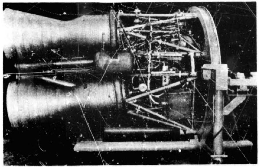 Figure 10-26.-Dual-engine cluster.
Still another approach for ballistic missiles is the combination (clustering) of a pair of booster engines with a large-expansion-area sustainer engine. During flight, the booster engines may be jettisoned following the boost period, while the sustainer continues, fed from the same tanks. These configurations are also referred to as "One-and-one-half-stage vehicles."
Recent Cluster Design Trends
The first clustered engine vehicle, signifying the modern trend toward multipurpose engines, is NASA's S-1 first-stage booster for the Saturn I. It is powered by 8 LOX/RP-1 engines, the basic elements of which were transplanted with relatively minor modifications from earlier engines. The S-1 is noteworthy for its tank arrangement. Eight tanks from an earlier missile are clustered around a central larger tank. This "multicellular" design, which in the case of the S-1 permitted early availability of large tank capacity without major retooling, has been recommended by some vehicle designers for still larger vehicles. The eight engines of the S-1 are grouped into four fixed inner and four gimbaled outer engines. Except for the outer-engine actuatois, all eight are identical, independent units, built and issted singly, and combined for the first time on the vehicle proper.
In the S-1, the number of engines was, no doubt, almost entirely governed by the availability of existing major engine components and tankage. For subsequent vehicles, such is the Saturn V three-stage vehicle, greater freedom existed. particularly with respect to the optimi-
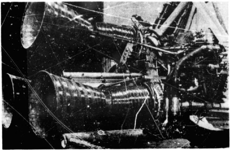 Figure 10-27.-Three-engine cluster.
zation of thrust and total impulse (propellant load).
To examine some of the considerations which govern engine cluster arrangements, we assume that payload and mission of a multistage vehicle are defined and that stage propellant loads (total impulse) and tank geometry (diameter) have been optimized. We further assume that engines are available and will not be redesigned, and that the optimum thrust for a typical stage suggests a range of from four to six engines. An analysis has shown that payload performance probably increases with the larger number of engines (fig. 10-28); however, there are other considerations.
One of the most influential considerations is "Engine Out Capability" for increased vehicle reliability (also see ch. II, "Thrust Level"). Specific engine provisions for engine-out (EO) are summarized in section 10.9. Capability of a vehicle to complete its mission with one engine inoperative always entails some performance losses. However, these losses decrease with increasing total number of engines, because less performance reserve is needed, and because less correcting thrust vector trim is required from the operating engines. Trim from engine-out is further affected by the diameter of the enginemounting circle. The contribution to mission reliability by EO capability is substantial, witn cluster failure potential reduced by more than half. In addition, absolute reliability values are a function of the number of engines in the cluster. This is most evident with no engine-out.
Figure 10-29 illustrates this at two points of time of engine overall development status. As the latter progresses, the difference between
ENGINE SYSTEMS DESIGN INTEGRATION
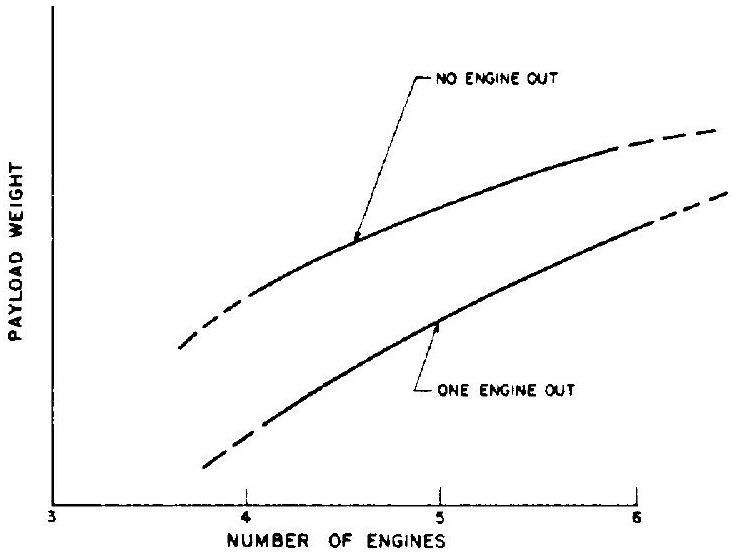 Figure 10-28.-Stage-payloadweight as a function of number of engines in cluster.
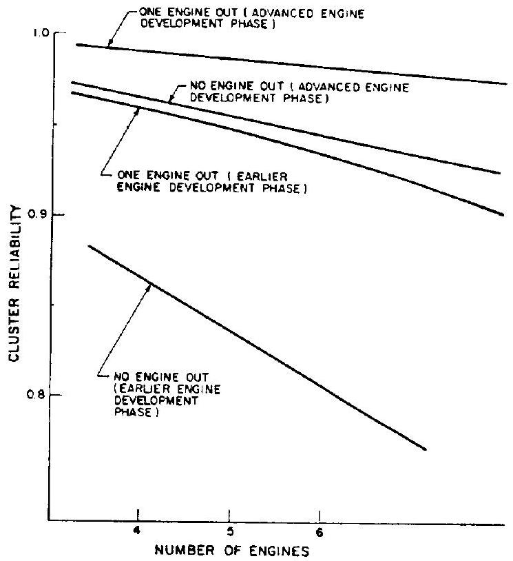 Figure 10-29.-Typical cluster reliability prediction as a function of number of engines in cluster and of development time.
engine-out and no engine-out narrows (see also table 2-2). It may be stated that for a given number of vehicle flights, the benefits of engineout capability are the greater, the lower the single-engine reliability. Figure 10-28, in combination with figure 10-29, shows that simultaneous addition of one engine and inclusion of engine-out capability retain about the same pay- load for a substantially higher cluster reliability at any single-engine reliability level.
Another important consideration is cluster diameter in relation to vehicle diameter. As will be discussed in section 10.9, it is mandatory that all engines fit into the interstages from which they must separate without interference. This restriction is not valid for the first stage, where engines may protrude beyond the tank profile. The degree of protrusion, however, must be balanced against drag losses.
Specific considerations for each chosen number of engines follow (fig. 10-30).
4-Engine Cluster
This configuration provides the lowest total thrust in the established band of 4 to 6 engines, but it is optimum for engine interchangeability. All four engines will be gimbaled. Only one installation is required: all inlet ducts and other engine to stage connections can be made id-1tical. The thrust vector control mode is simplest: all engines deflect in pitch and yaw, and all actuators participate equally in roll control (fig. 10-30(a)).
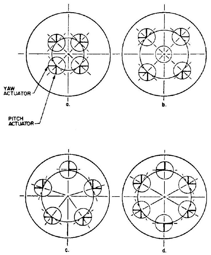 Figure 10-30.-Typical engine cluster arrangements.
5-Engine Cluster
This number provides greater thrust, but complicates matters in other respects. Two basic arrangements are possible, as shown in figure 10-30(b) and (c). The arrangement with center engine is preferred. The center engine is mounted fixed; i.e., stiff arms are installed in place of gimbal actuators. It is advisable to install the engine with complete gimbal bearing for standardization and ease of alinement. With the remaining four engines gimbaled and grouped as in a 4 -engine cluster, the same benefits are derived as with the latter. However, because of the center engine, two installations are required. Furthermore, two sets of inlet ducts are needed, their different length affecting pressure drop and fluid velocity profile (engine turbopump NPSH), water hammer from closure of valves (valve timing), trapped propellants, and possibly insulation requirements (weight penalties and complexity). Figure shows a typical 5 -engine installation with fixed center engine.
With all five engines arranged on a circle, the basic engine package may become more uniform, since all will be gimbaled. However, three different installations are required (fig. 10-30(c)),
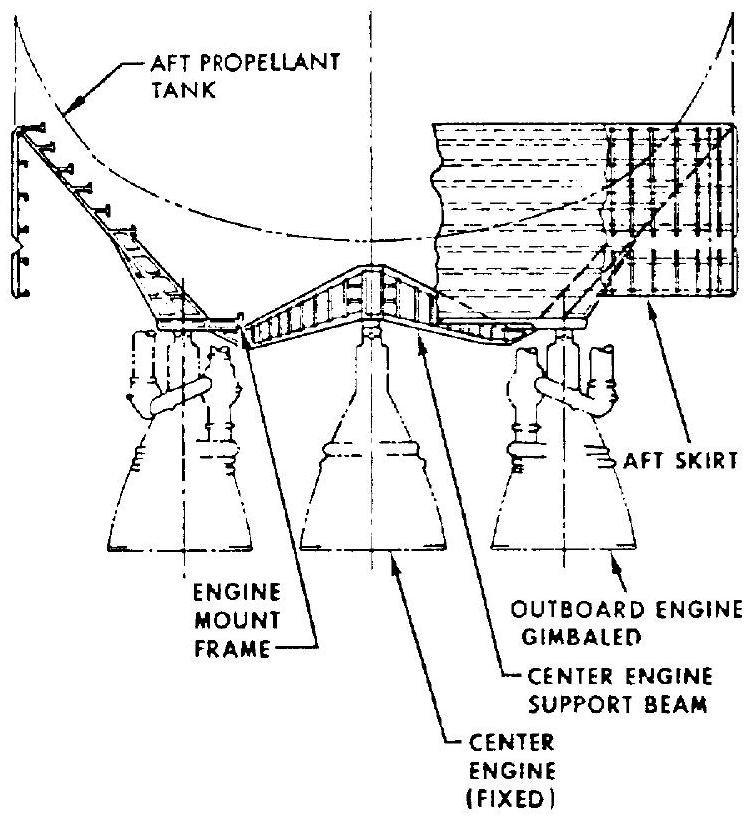 Figure 10-31.-Typical five-engine cluster configuration. Center engine fixed, four outer engines gimbaled.
and systems thrust vector control response is seriously affected, due to roll and yaw coupling, particularly under malfunction conditions. As to mounting-circle diameter, the two 5 -engine clusters are about equal.
6-Engine Cluster
This combination provides the highest thrust, at the expense of a larger mounting circle. This in turn increases the effects of one-engine-out on trim required and may compound interstage and interengine clearance problems. The control mode is comparable to the four engine cluster in simplicity. The 6 -engine cluster requires two installations, with inlet and other effects similar to those discussed with the 5 -engine configuration.
This cluster offers the potential of removing (not installing) 2 engines and still retaining a satisfactory 4 -engine combination, which provides added flexibility at minimum scar weight (i.e., weight of components that cannot readily be removed along with the engines).
If at all possible, the engine designer should specify that the engine intended for cluster use be tested under conditions closely simulating vehicle installation. It may be expected that the vehicle builder will conduct a firing program of his own; however, this nust be devoted to cluster behavior and performance evaluation, and should not deteriorate into continued single engine development. A major difference between single engine and cluster firing is in the base conditions, i.e., the heat and pressure environment of the engines, particularly at altitude. Flame radiation effects, backwash of combustion gases, and impingement may create much more severe conditions than are present during singleengine firing. The pressure environment produced by several engines firing together may create moments on the engines which must be accounted for in the design of the gimbal system. The engine designer should be familiar with these conditions so that his claim that the engine can be clustered remains valid after delivery.
Awareness by the engine designer of the considerations governing engine clustering, as presented here, will enable him to complete his systems integration with a broader view to application.